
This blog post will comprise the necessary steps to design a 3-tier architecture in AWS.
What is 3-Tier Architecture?
The three-tier architecture stands as one of the predominant and widely adopted architectural paradigms in the software industry. It essentially revolves around the concept of dissecting our software application into three distinct and interconnected components, each playing a specific and crucial role in the overall functionality of the system. These three primary layers, known as the web layer, the application layer, and the data layer, collectively form a robust and organized framework for designing and managing complex software systems.
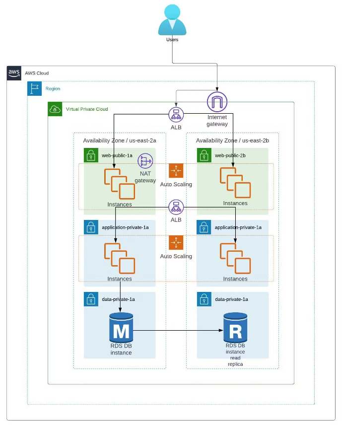
Architectural Diagram
Components of 3-tier architecture
Web Tier (Frontend)
This layer is the top level of the software application. Users can see the displayed information and interact with our application using a web browser. This layer consists of Engaging web pages, and dynamic forms which are used to send information to the application layer which processes the data and stores that information in the data layer.
Application Tier (Backend)
This layer is the middle layer, acting as a bridge between the web layer and the data layer. It has all the business logic that supports the application’s core functionality. It performs data validation coming from the web layer and also interacts with the data layer to store that information.
Data Tier (Databases)
This layer is the final layer of the architecture and is used to store all user-related information. This ensures that the data can be easily retrieved when needed.
VPC setup
AWS VPC is a virtual private cloud which is a dedicated private network in which you can launch your resources in an isolated network.
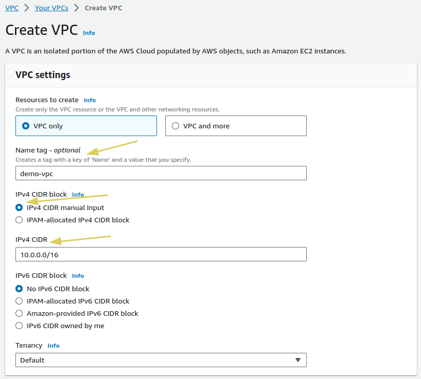
- Open the AWS console, type
VPCin the search bar, and selectCreate VPC. This will open the VPC creation console:

- For VPC settings, enter the name
demo-vpc, select the IPv4 CIDR block, input10.0.0.0/16for the CIDR, and then selectCreate VPC.
Subnets
A subnet is a portion of the network that offers additional resource isolation and control over the resources launched in our VPC. A subnet cannot span across multiple availability zones and should reside in a single AZ.
NOTE: We will be needing 6 subnets in total (two for the web layer, two for the application layer, and two for the data layer)
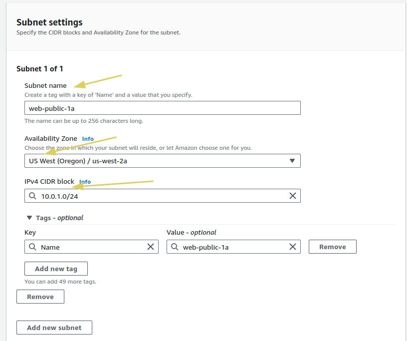
- In the VPC console, navigate to
Subnetsin the right panel and selectCreate Subnet. - Select the VPC
demo-vpc, which we created in our VPC setup section. - For the Subnet settings, name the subnet
web-public-1achoose Availability Zoneus-east-2a, and set the IPv4 CIDR block to10.0.1.0/24.
- Similar to the
web-public-1asubnet, we will create the remaining subnets for the application and data layers. Below are the subnet names, availability zones, and CIDR ranges:
| Subnets | Availability Zone | CIDR |
| web-public-1a | us-east-2a | 10.0.1.0/24 |
| web-public-2b | us-east-2b | 10.0.2.0/24 |
| application-private-1a | us-east-2a | 10.0.3.0/24 |
| application-private-2b | us-east-2b | 10.0.4.0/24 |
| data-private-1a | us-east-2a | 10.0.5.0/24 |
| data-private-2b | us-east-2b | 10.0.6.0/24 |
Internet Gateway
The Internet Gateway serves as an intermediary between our VPC and the Internet. Any traffic originating from our VPC and destined for external destinations, such as the public internet, is routed through the internet gateway.
- Navigate to the
InternetGatewaysection in the VPC console. - Select
CreateInternetGateway. - Enter the name for your Internet Gateway, such as demo-IGW
. - Click on the
Create Internet Gatewaybutton to create it.
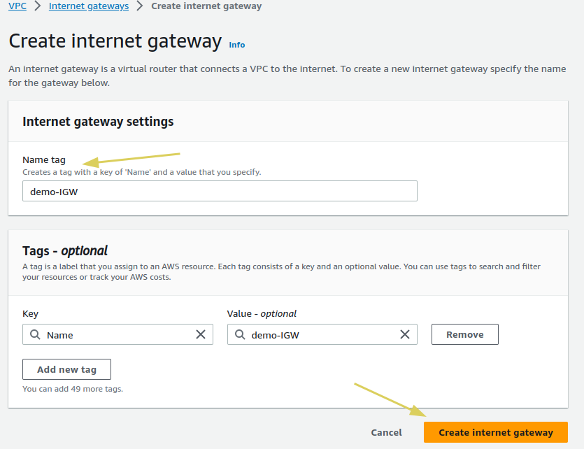
- When an Internet Gateway is created, attach it to the existing VPC.
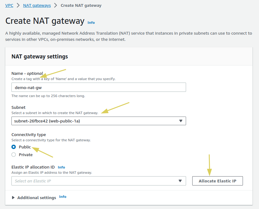
NAT Gateway
A Network Address Translation (NAT) Gateway is used to allow resources within a private subnet in a Virtual Private Cloud (VPC) to access the internet while keeping them hidden and protected from direct access. It’s important to note that a NAT gateway must always be launched in a public subnet.
To create a NAT Gateway in the console, follow these steps:
- Navigate to the Internet Gateway in the console.
- Select
Create NAT Gateway. - In the NAT Gateway settings, enter the name
demo-nat-gw. - Choose a public subnet, such as
web-public-1a, for the subnet. - Allocate an Elastic IP for the NAT Gateway.
- Click
Create NAT Gatewayto complete the process. - It will take approximately 2 to 5 minutes for it to become available.
Route Tables
The route table defines the pathways for the VPC network. It contains a set of rules, called routes, that determine where network traffic from your subnet or gateway is directed.
- Navigate to the route table section.
- Select
Create Route Table. - Enter the name
web-RTfor the route table. - Choose your VPC from the available options.
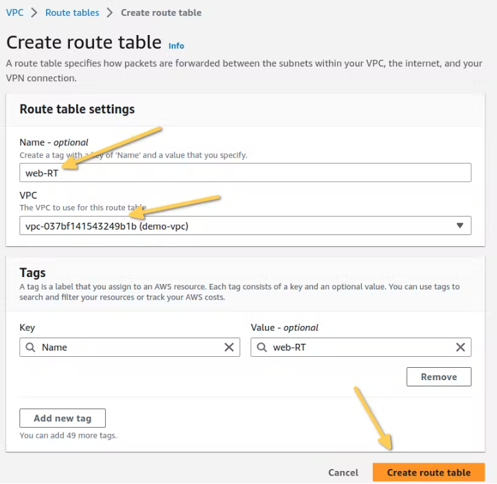
- For the
application-RT and data-RTroute tables, follow the same steps as we did forweb-RT.
Subnet Associations
After creating the route tables, we need to associate subnets with their respective route tables.
| Route Table | Subnet Association |
| web-RT | web-public-1a , web-public-2b |
| application-RT | application-private-1a, application-private-2b |
| data-RT | data-private-1a, data-private-2b |
Adding route
- Navigate the route table
web-RTand edit the route. - Since
web-RTis a public subnet, we will add an internet gateway as an entry and exit point for traffic entering and exiting the public subnet.
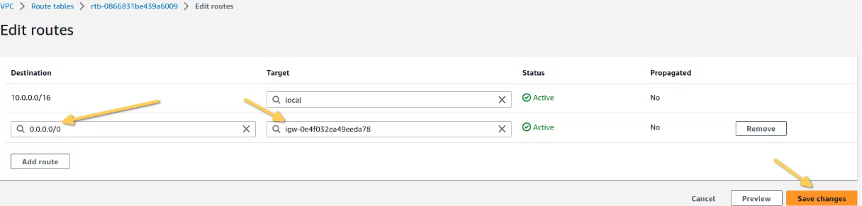
- For the
application-RTanddata-RTroute tables, we will add a NAT gateway to ensure all the private resources can be accessible via the NAT gateway.

Load Balancing
Elastic load balancer (ELB) plays a vital role in our application architecture. Its responsibility is to evenly distribute traffic to the servers. Additionally, It continuously monitors the health status of these servers. If a server is found to be offline or unhealthy, the ELB temporarily suspends sending requests to it until it becomes healthy again.
Open the load balancer console and click on Create Load Balancer. We will be using an Application Load Balancer, so select the Application Load Balancer as the type.
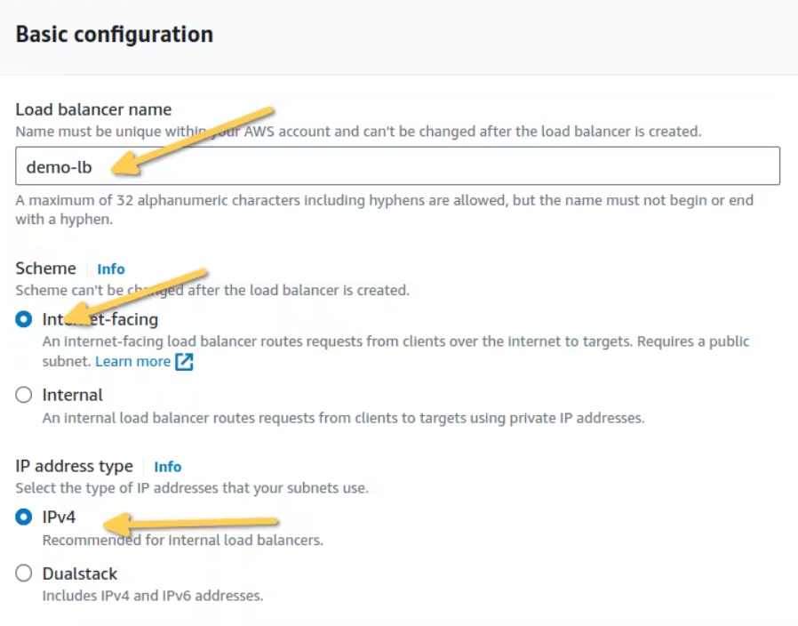
Basic configuration of ELB
These are the settings we will use to configure our load balancer:
- Load Balancer Name:
demo-lb - Scheme:
Internet-facing - Address Type:
IPv4
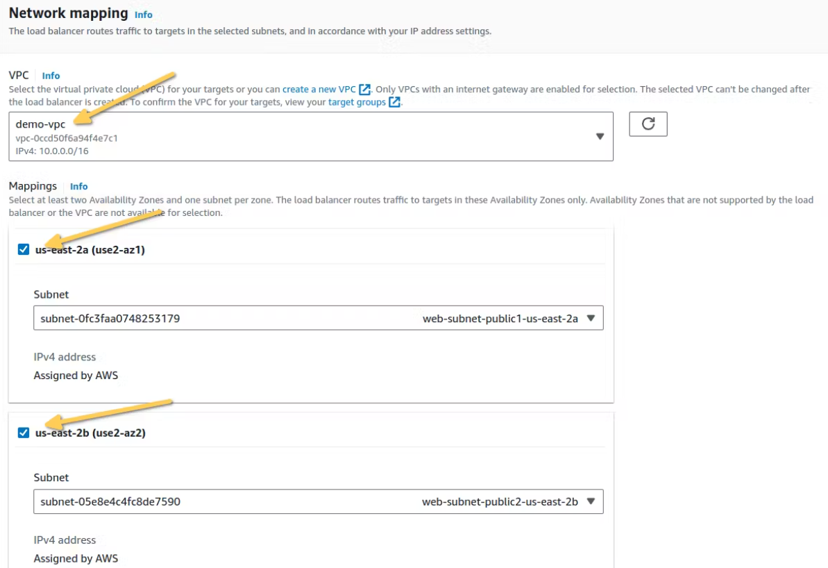
Network mapping
Here are the network settings for our load balancer:
- VPC:
demo-vpc - Mappings:
web-public-1a & web-public-2b - Security Group:
load-balancer-sg
Note: You must create a separate security group for the load balancer, which should include two inbound rules for HTTP on port 80 and HTTPS on port 443.
Listeners and Routing
Listeners, as the name suggests listen for an HTTP and HTTPS protocol and forward that request to the appropriate target group.
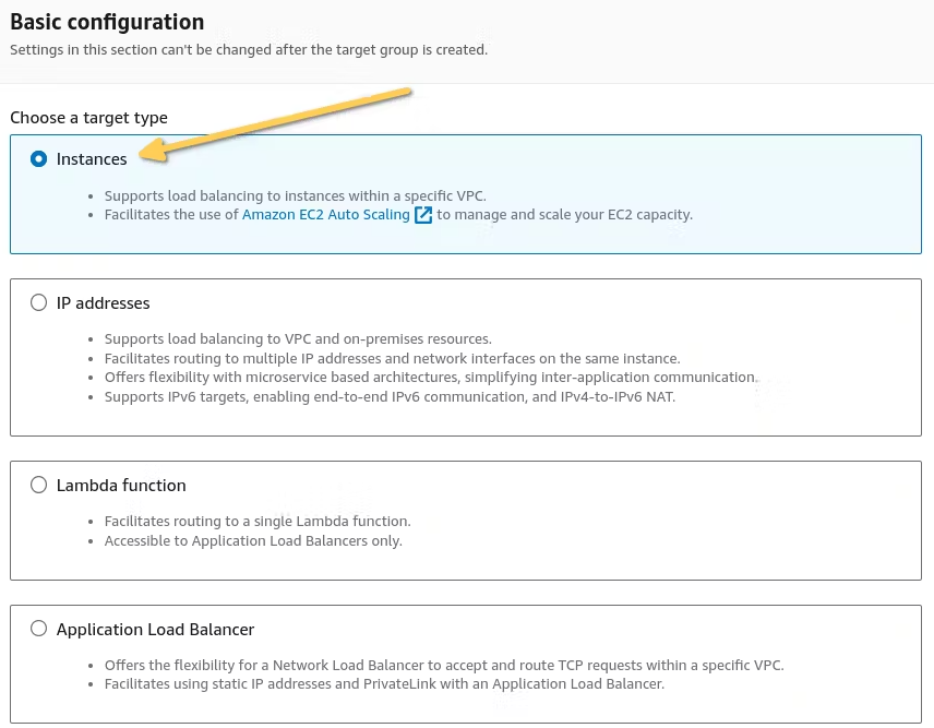
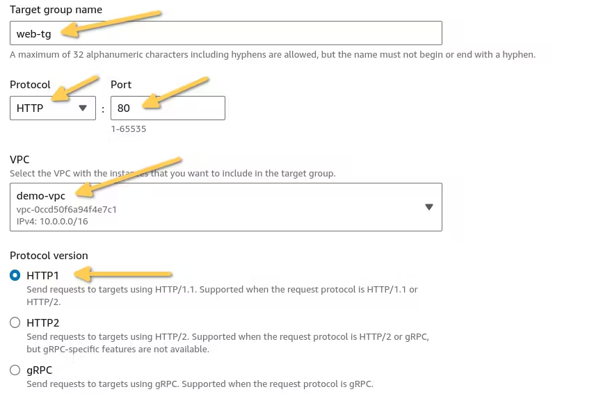
First, we need to create a target group. Navigate to the target group page and proceed with creating the target group.
- Choose a target type:
Instances. - Target group name:
web-tg. - Protocol: HTTP & Port: 80.
- Select your VPC. In my case, I will be selecting
demo-vpc. - Skip the next part and click on
Create Target Group.
- Now, go back to the Load Balancer page and select the Target Group we just created.
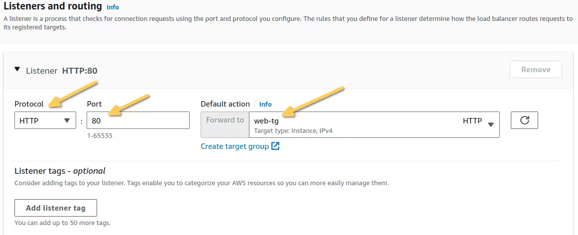
- Once you have completed all the requirements, click
Create Load Balancer.
AutoScaling Groups
An Auto Scaling group is a way to group EC2 instances for automated scaling and streamlined management in AWS. It automatically adjusts the number of instances based on predefined rules, ensuring efficient resource utilization and application performance.
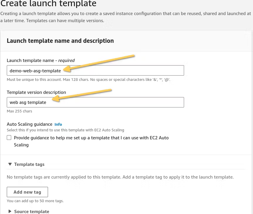
Creating Launch Template For Web Server
- In the ec2 console, navigate to
launch templatesand create a launch template. - Launch template name:
demo-web-asg-template. - Template version description:
web asg template.
- We will be using the
Amazon Machine Image (AMI)from 2023; you can choose any AMI of your preference. - For the instance type, choose
t2.micro, which is free-tier eligible, ensuring that we won’t incur charges for the instances we launch. - If you’ve already created a key pair, select that. If not, create a new key pair and use it.
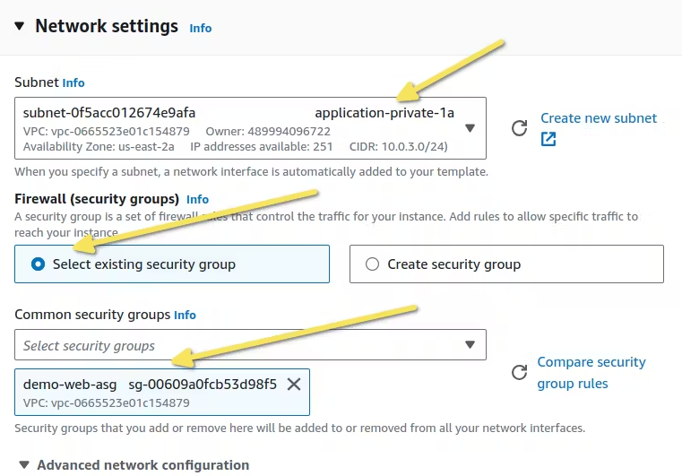
- In the network settings, choose the following settings for the subnets
application-private-1aorapplication-private-1b. For the security groups, you can choose an existing one or create a new one. I’m using a security group that I’ve already created for my web server, i.e.,demo-web-asg.
- To add our user data script for installing the Nginx web server, navigate to the
Advanced Detailssection, scroll down to the bottom, and in theUser Datasection, insert the following script:
#!/bin/bash
yum update -y
yum install nginx -y
systemctl enable nginx
systemctl start nginx- After adding the user data script, click on
Create Launch Template.
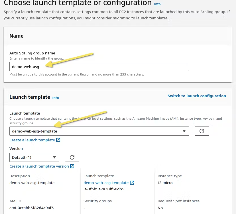
Creating AutoScaling group
Now that we have created our blueprint for the auto-scaling group, it’s time to launch instances from that blueprint using an auto-scaling group.
- Navigate to the ec2 console, navigate to the autoscaling section and select auto-scaling groups.
- Name your auto-scaling group as
demo-web-asgand for the launch template, selectdemo-web-asg-template, which we created in the previous section.
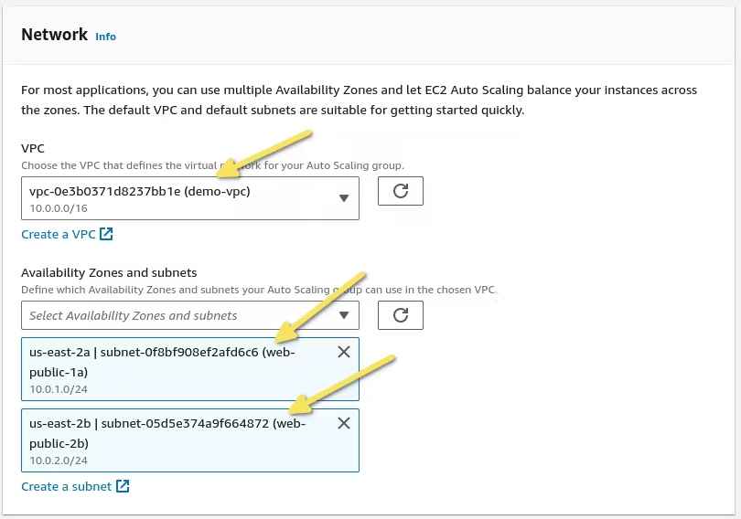
- In the network section of our auto-scaling group, choose our VPC,
demo-vpc, and the Availability Zones and subnetsweb-public-1aandweb-public-2b.
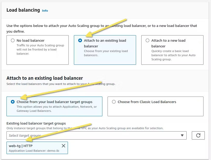
- For Load Balancing, choose the load balancer we created in the previous section,
demo-lb, and for the target group, selectweb-tg.
For the group size. We have 3 options:
- Desired capacity: This represents the initial count you set, which can be scaled up or down based on our metrics settings and policies.
- Minimum capacity: This sets the minimum number of instances that can be reached through scaling down, based on specific metrics and policies.
- Maximum capacity: This defines the maximum number of instances that can be reached through scaling up, based on specific metrics and policies.
- As we currently don’t have any applications running, skip the scaling policies.
- After completing all the information for our auto-scaling group, review your auto-scaling group settings and then click on
Create Auto Scaling group. - After creating our auto-scaling group, wait for the instances to reach a healthy state.
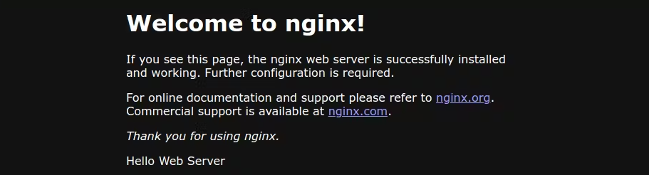
- Once the instances inside our auto-scaling group become healthy, copy the DNS of the load balancer and paste it into your browser. You should see the Nginx welcome message:
Relational Database
AWS RDS is service that caters to various types of database engines and is used for relational data storage. We will be using AWS RDS for this use case.
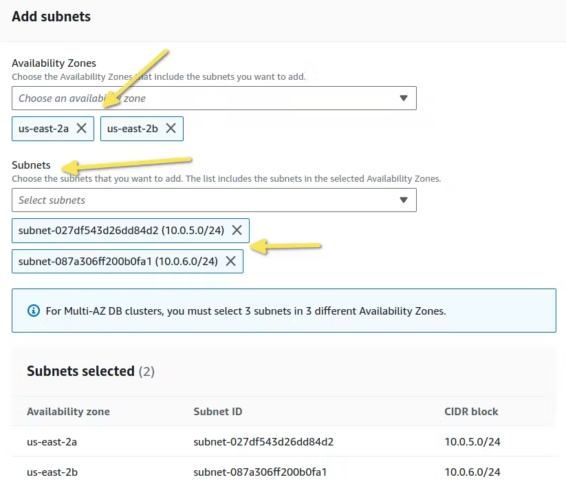
Creating Subnet Group for AWS RDS
Before launching our RDS instance, we need to create a subnet group, which is a collection of private subnets dedicated to our database instances.
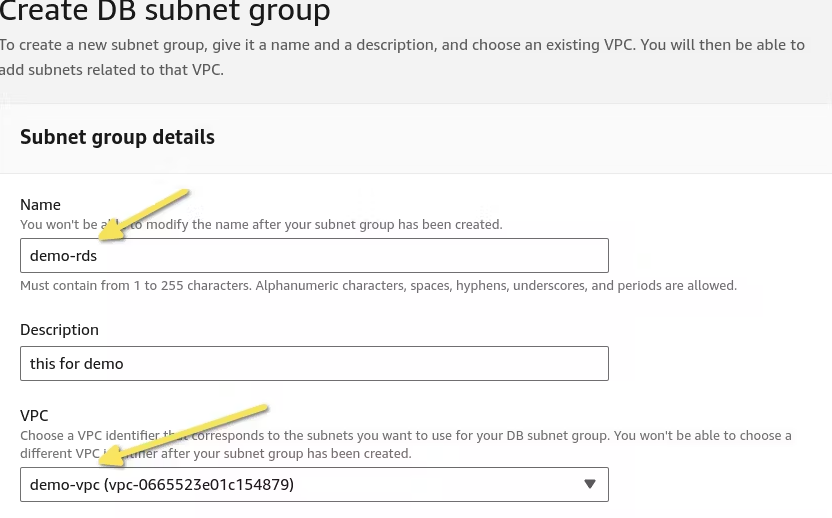
- In the AWS console, search for RDS and navigate to
Subnet Groups. - Choose a name for your subnet group:
demo-rds. - Select VPC:
demo-vpc.
- Select the availability zones for the RDS:
us-east-2a,us-east-2b. - For the subnets, we will choose our data subnets:
data-private-1aanddata-private-2b.
Launching RDS
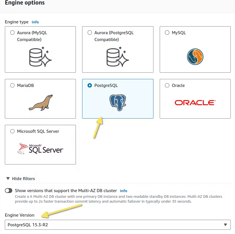
In the AWS RDS console, navigate to Databases and create a database. We will be using PostgreSQL for the use case.
- Select the standard method for creating the DB instance.
- Since we’re using PostgreSQL as our database, choose the PostgreSQL engine and select the latest engine version.
- We will select a
Dev/Testtemplate. For simplicity and cost-effectiveness, and will use aSingle DB instance.
General setting for the instance:
- DB Instance Identifier:
demo-rds. - Master Username:
demo - Choose a strong password for the master database user.

For instance configurations:
- You can choose the instance class as per your use case. we will be using the Burstable class ( t class instance series).
- As for the storage type, we will use
gp3as suggested by default and allocate100GBof storage.
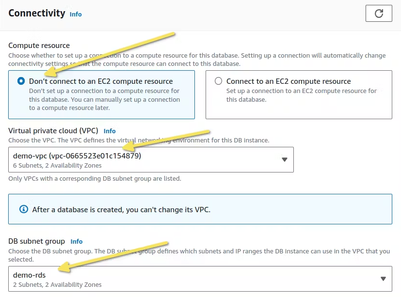
We need to configure the connectivity for our instance so it can communicate with our application. Following are the RDS connectivity settings:
- For the VPC, We will use our
demo-vpc. - For the DB subnet group, choose the
demo-rdssubnet group we created in the previous section.
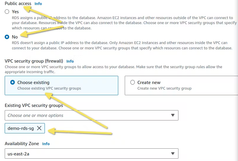
- We don’t want our data to be publicly accessible, so select
Nofor the Public access settings. - We need a security group so that other applications inside our VPC can connect to our database instance. You can either create a security group for your instance or use an existing one. We have already created a security group before hand for the DB instance, i.e.,
demo-rds-sg. - Since our instance is a single instance, we need to select an availability zone for our instance, which is
us-east-2.
- For the rest of the settings, there’s no need to make any changes. The default settings are sufficient. Once everything is configured, click the
Create Database button. - The database instance will take approximately 10 to 15 minutes to become available.
Conclusion
Implementing a three tier architecture in AWS offers a robust and scalable framework for building modern web applications. By dividing the application into distinct web, application, and data tiers within the AWS ecosystem, businesses can harness the power of cloud computing to achieve robustness and scalability. That is all you need in order to create a three tier architecture in AWS. Using this structure, you can now deploy your applications and services efficiently.

A community-first thinker who brings people together around shared passion and purpose.